What Is CAN Bus and How Does It Relate to OBD2 Diagnostics
By Kamil Siegień / October 12, 2026
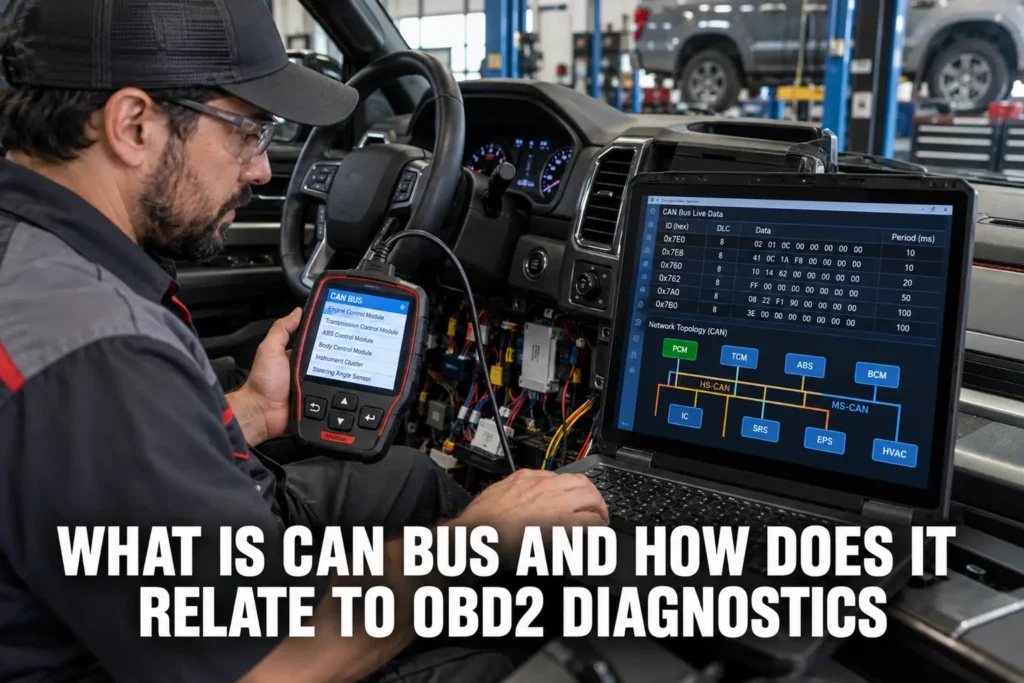
CAN bus (Controller Area Network bus) is the communication backbone that connects the electronic control modules in modern vehicles. Every sensor value, module command, and diagnostic message that a scanner reads or sends travels over the CAN bus. Understanding what CAN bus is, how it works, and how it differs from the older communication protocols it replaced explains why newer vehicles require CAN-compatible scanners, why communication faults appear as U-codes in scanner data, and why the OBD2 diagnostic interface works the way it does on vehicles built after 2008.
I explain this in more detail in my my guide on use an.
For scanner recommendations to perform this type of work, see my best diagnostic scanners.

About the author: Hello! I’m Kamil Siegień, founder of OBD2 Scout. My diagnostic experience started with an engine rebuild on a 2014 Skoda Superb 1.8 TSI, where tuning from 160 to 222 hp required mastering live data and ECU behavior that basic code readers cannot handle. I am a former BMW and MINI employee and regularly use diagnostic scanners on my own Audi A4 2.0 TFSI.
This guide covers how CAN bus works, why it replaced earlier vehicle communication protocols, the different CAN bus speeds used for different systems, how CAN bus connects to the OBD2 diagnostic interface, how to identify CAN bus faults in scanner data, and what U-codes mean in a scan report.
I explain this in more detail in my my guide on check used car.
For a scanner that handles ABS and SRS diagnostics, check my scanners for ABS and SRS diagnosis.
How CAN Bus Works
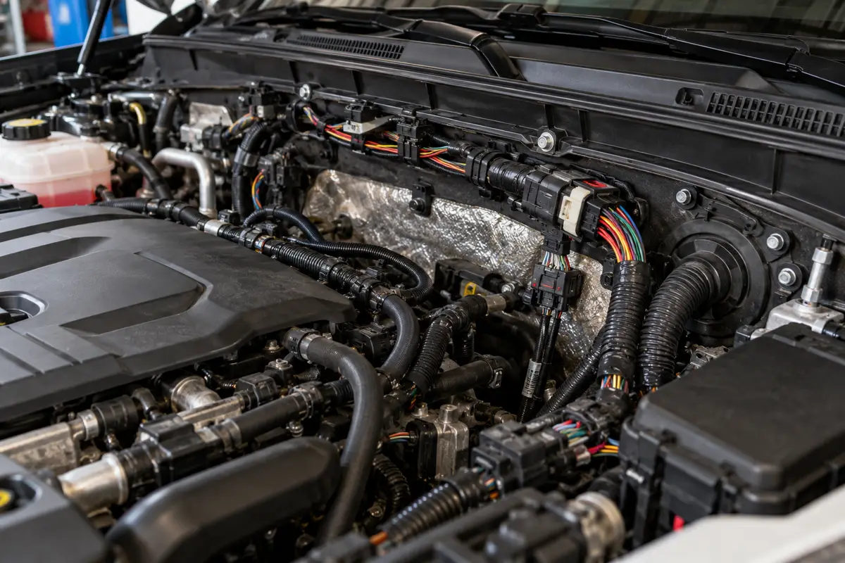
CAN bus is a two-wire differential serial communication system. The two wires are called CAN-High and CAN-Low. In a dominant (logic 0) bit state, the CAN-High wire is driven to approximately 3.5 volts and the CAN-Low wire is driven to approximately 1.5 volts, creating a 2-volt differential. In the recessive (logic 1) state, both wires float to approximately 2.5 volts, producing a near-zero differential. The receiving modules detect the bit state by measuring the differential voltage rather than the absolute voltage on either wire, which makes the system highly resistant to electrical noise: noise that affects both wires equally (common-mode noise) cancels out in the differential measurement.
I explain this in more detail in my does obd2 work on electric cars.
If you prefer a wireless setup, my best wireless diagnostic tools covers the best options.
All modules on a CAN bus share the same pair of wires and can each be a transmitter and a receiver. When a module has a message to send, it arbitrates for bus access: each module begins transmitting its message identifier bits simultaneously. Since a dominant bit overwrites a recessive bit, lower-priority messages (higher identifier numbers) automatically lose arbitration to higher-priority messages without any collision or data loss. The losing module detects it has been overridden and waits until the higher-priority message finishes before attempting again. This collision detection and automatic priority arbitration mechanism is what allows multiple modules to share a single two-wire bus efficiently without a central controller managing traffic.
My obd2 codes after car accident covers this step by step.
Audi owners looking for the right scanner should check my top-rated scanners for Audi.
Each module on the bus monitors all traffic, including traffic not addressed to it, and captures messages relevant to its operation. The ECM broadcasts engine speed on the CAN bus: the instrument cluster module listens and displays it, the TCM listens and uses it for shift timing, and the ABS module listens and uses it for traction control calculations, all from the same single broadcast message. This broadcast architecture eliminates the need for dedicated point-to-point wiring between modules that need to share data.
My my guide on reset transmission adaptations covers this step by step.
Honda owners looking for the right scanner should check my top-rated scanners for Honda.
CAN Bus vs Earlier OBD2 Protocols
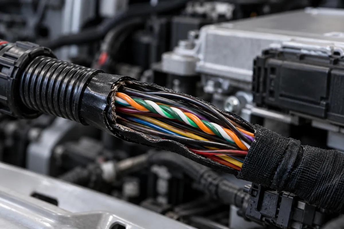
Before CAN became universal, OBD2 communication used several older protocols depending on the manufacturer. ISO 9141-2 (used by European and Asian manufacturers) and KWP2000/ISO 14230 were single-wire serial protocols operating at low data rates (10,400 baud). SAE J1850 PWM (used by Ford) and J1850 VPW (used by GM) were American variants with different electrical characteristics. All of these protocols share a fundamental limitation: slow data rates and sequential communication, where the diagnostic tool polls one parameter at a time and waits for the response.
BMW owners looking for the right scanner should check my top-rated scanners for BMW.
CAN bus (ISO 15765-4 for OBD2 use) operates at 500 kbits per second (high-speed CAN) or 250 kbits per second (mid-speed), which is 25 to 50 times faster than the older protocols. This speed increase allows a scanner to retrieve dozens of live data parameters simultaneously and update them multiple times per second rather than polling one at a time. It also allows the scanner to send and receive complex multi-frame messages for service functions and ECU programming, which older protocols could not support efficiently.
My ecu coding when does it need to be done explained covers this step by step.
I explain this in more detail in my can you drive with check engine light on.
If you are on a tight budget, my best value OBD2 scanners covers the top value picks.
The EPA mandated CAN as the required OBD2 communication protocol for all vehicles sold in the US from model year 2008 onward. This ended the confusing multi-protocol era: a scanner built after 2008 that supports ISO 15765-4 CAN connects reliably to any US-market vehicle from 2008 forward without needing to detect and adapt to different protocol variants. Pre-2008 vehicles may still use any of the older protocols, which is why scanners that cover older vehicles need multi-protocol support.
Ford owners looking for the right scanner should check my best diagnostic tools for Ford.
Multiple CAN Networks in a Single Vehicle
Modern vehicles do not have a single CAN bus connecting all modules. They have multiple CAN networks operating at different speeds, segregated by functional area. A typical architecture includes: a high-speed powertrain CAN (500 kbits/s) connecting the ECM, TCM, ABS/ESC module, and instrument cluster; a mid-speed body CAN (250 kbits/s or 125 kbits/s) connecting the BCM, door modules, HVAC, and comfort systems; and often additional specialized networks for infotainment, driver assistance, and chassis systems. A central gateway module connects these separate buses and routes specific messages between them (the ECM’s engine speed on the powertrain bus is shared to the body bus through the gateway for modules that need it).
Chevy owners looking for the right scanner should check my top-rated scanners for Chevy.
For OBD2 diagnostics, pins 6 (CAN-High) and 14 (CAN-Low) of the OBD2 connector are connected to the high-speed powertrain CAN bus where the ECM lives. A scanner that connects to these pins communicates with the powertrain bus directly. To access modules on other buses (body modules, HVAC, airbag on some vehicles that are on a separate bus), the scanner communicates through the gateway module, which routes the diagnostic requests to the appropriate sub-bus. The gateway’s routing function is why a scanner with full system scan capability accesses all modules despite physically connecting only to the powertrain CAN pins.
My airbag srs codes explained covers this step by step.
My what is a full system scan obd2 scanner covers this step by step.
Toyota owners looking for the right scanner should check my top-rated scanners for Toyota.
CAN Bus Faults and U-Codes
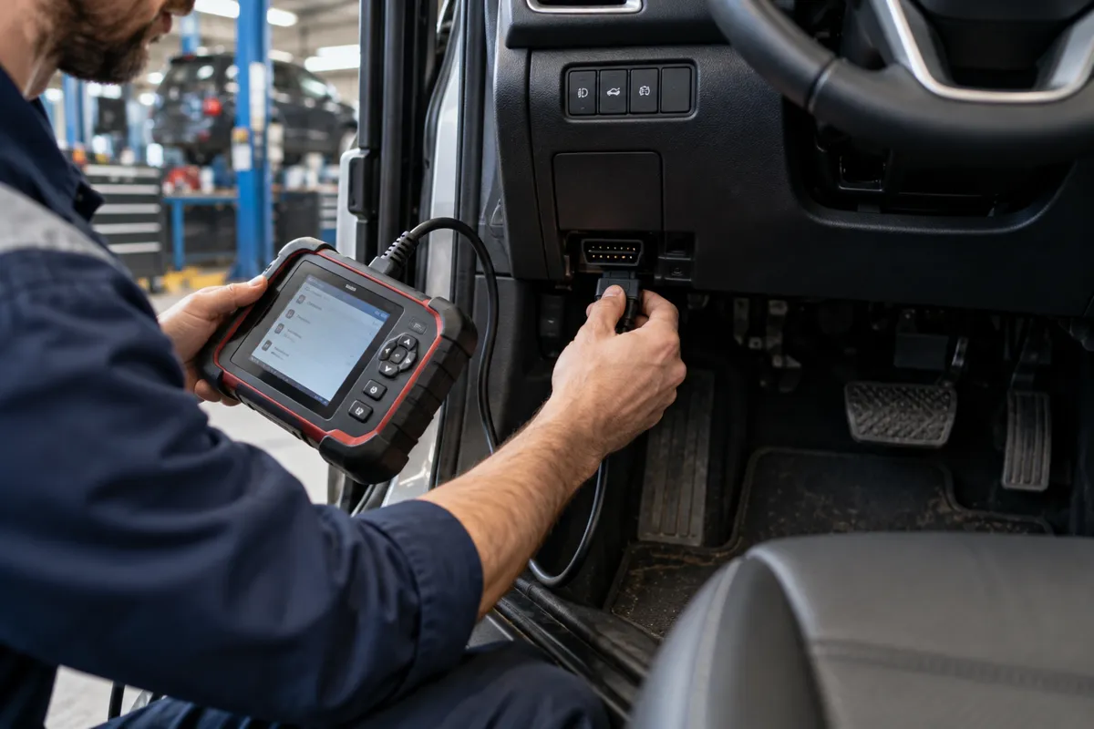
Communication faults on CAN bus are stored as U-codes (Unified or Network codes). U-codes indicate that a module attempted to communicate with another module and received no response, received a response with invalid data, or detected a physical bus fault. Common U-code types include: U0001 (high-speed CAN bus communication fault), U0100 (lost communication with ECM/PCM), U0121 (lost communication with ABS control module), U0155 (lost communication with instrument cluster), and dozens of others corresponding to each module in the vehicle’s network.
Mercedes owners looking for the right scanner should check my top-rated scanners for Mercedes.
When a module drops off the CAN bus (due to loss of power, a failed module, or a wiring fault on the bus), every other module that expected to receive messages from it stores a lost communication U-code. A vehicle with a failed ABS module may store U0121 in the ECM, the TCM, the body control module, and the instrument cluster simultaneously. This creates a scan report with four U-codes that all point to one root cause. Identifying the common denominator module in a multi-U-code scan report typically identifies the failed or disconnected module faster than addressing each code individually.
Honda CR-V owners can find the right scanner in my top diagnostic tools for the CR-V.
Physical CAN bus faults (a broken CAN-High or CAN-Low wire, or a short between the two wires) cause the entire bus to fail rather than a single module, producing U-codes in every module connected to that bus segment. These bus-level faults are diagnosed with a multimeter: measuring the resistance between CAN-High and CAN-Low with the ignition off and the terminating resistors present should read approximately 60 ohms (two 120-ohm termination resistors in parallel). Readings well above or below 60 ohms indicate a break in one wire or a short between them.
Audi Q8 owners can find the right scanner in my best scanners for the Q8.
LIN Bus and Other Supplementary Vehicle Networks
CAN bus handles high-priority, high-speed communication between major control modules. Simpler components that do not need high data rates or real-time communication use a different, lower-cost protocol: LIN bus (Local Interconnect Network). LIN bus is a single-wire serial protocol operating at 19,200 baud, significantly slower than CAN. It connects simple actuators and sensors to a master module via a single wire rather than the two-wire CAN differential pair. Common LIN bus applications include: individual seat heater controls, mirror adjustment motors, rain sensor data, power window modules on doors, steering column adjustment motors, and individual HVAC blend door actuators.
Audi Q7 owners can find the right scanner in my best scanners for the Q7.
In a typical architecture, the BCM acts as the LIN master and communicates with multiple LIN slave nodes (the individual seat, window, or mirror modules) over a single LIN bus wire. The BCM then reports relevant data from these LIN slaves onto the main CAN bus for other modules that need it. From the OBD2 scanner’s perspective, it never sees the LIN bus directly: it communicates with the BCM (or other master modules) over CAN, and the master handles the LIN communication internally. Faults in LIN slave nodes appear as fault codes in the master module, not as direct CAN bus errors.
I cover this capability in more detail in my OBDLink MX+ deep dive.
More recent vehicles also implement MOST (Media Oriented Systems Transport) for high-bandwidth infotainment networks, FlexRay for safety-critical chassis control where CAN’s arbitration method introduces too much latency, and Ethernet (BroadR-Reach automotive Ethernet) for camera systems and domain controllers on high-spec vehicles. These specialized networks operate alongside CAN and serve specific bandwidth or latency requirements that CAN cannot meet. From a diagnostic perspective, communication faults on these networks still surface as U-codes in the modules that use them, interpreted through the same framework as CAN U-codes.
I cover this capability in more detail in my Innova 3100RS coverage.
FAQs
Can a faulty CAN bus cause a no-start condition?
Yes. The ECM on many modern vehicles requires CAN bus communication from other modules to start the engine. The body control module or immobilizer module confirms vehicle authorization over the CAN bus before the ECM activates the injection and ignition systems. A broken CAN bus that prevents this communication produces a no-start condition with no obvious visible cause: the engine cranks but does not fire, and the scanner cannot communicate with any modules on the affected bus segment. Diagnosing a no-start with no scanner communication as a CAN bus fault is a common misdiagnosis because the diagnostic approach normally depends on scanner communication.
Why do I get U-codes after replacing a battery?
Battery voltage drops during cranking can briefly disrupt CAN bus communication, especially if the battery is weak or the voltage drops below the modules’ minimum operating voltage. Modules that experience voltage below their minimum may log off the bus and store lost communication codes for other modules during the recovery period. These codes are historical: they occurred during the voltage event and do not represent an ongoing problem. Replacing a weak battery and clearing the codes resolves the entire code set. If U-codes return after a healthy battery is confirmed, a module itself or a bus wiring fault is the cause.
Is CAN bus the same on all vehicles?
CAN bus uses the same physical layer standard (ISO 11898) across vehicles, which means the electrical characteristics (differential voltage levels, bit timing at standard baud rates) are consistent. However, the messages broadcast on the bus, the module addresses, and the data format within each message are manufacturer-specific. A CAN bus analyzer captures the raw traffic on any CAN network, but interpreting what the messages mean requires either manufacturer-specific documentation (DBC files) or reverse engineering. Standardized OBD2 communication (ISO 15765-4) is a specific application layer built on top of CAN that uses a defined message format that is consistent across all OBD2-compliant vehicles.
Can I diagnose CAN bus problems with a standard OBD2 scanner?
A standard OBD2 scanner can read U-codes from modules that are accessible, which helps identify which modules have lost communication. However, a scanner cannot communicate with a module that is completely off the bus due to a power or wiring fault. More detailed CAN bus diagnosis (identifying which specific wire is broken, measuring bus voltages, observing bus traffic) requires either a dedicated CAN bus analyzer that captures and displays raw bus traffic, or a bidirectional professional scanner that can perform network topology tests on vehicles that support them. For most practical purposes, reading U-codes and cross-referencing them with the vehicle’s power and ground circuit to identify the failed module is the starting point.