
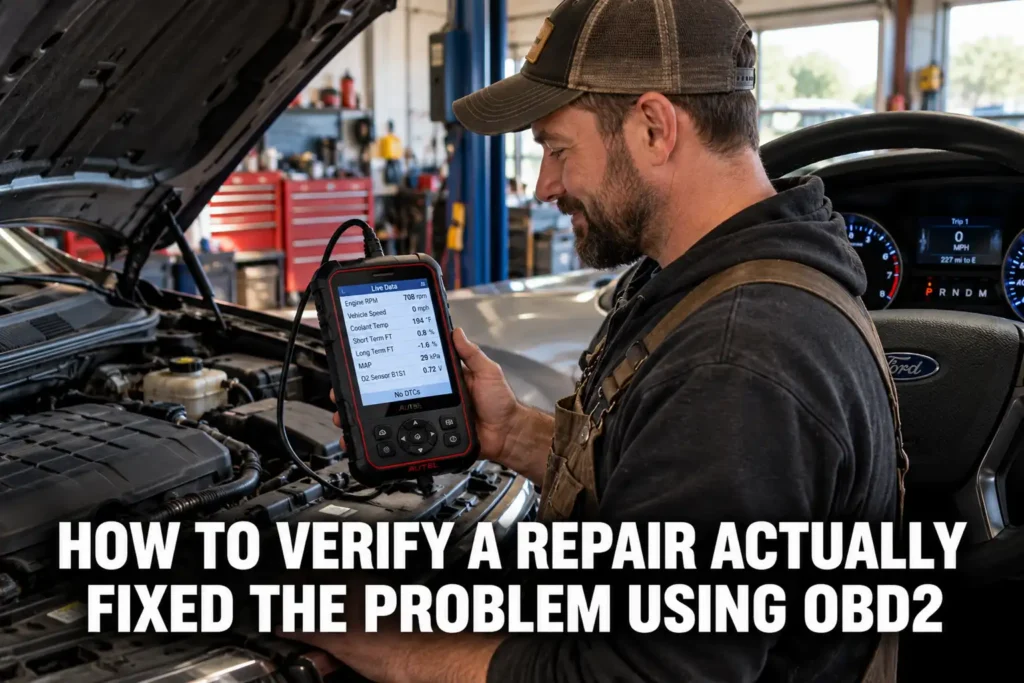
How to Verify a Repair Actually Fixed the Problem Using OBD2
By Kamil Siegień / October 12, 2026
Clearing a code after a repair and hoping it stays gone is not verification. A code that does not come back immediately may return days or weeks later when the monitor runs again under the right conditions. Proper repair verification using OBD2 tools provides objective evidence that the fault was genuinely resolved: the ECM ran its test, the system performed within specifications, and the code did not return. The difference between a confirmed repair and an unconfirmed one matters particularly for expensive repairs: replacing a catalytic converter at $400-$800 in parts deserves a Mode 06 check to confirm the new unit is performing well above the efficiency threshold, not just barely above it. This guide explains the process for verifying a repair with OBD2 data, which monitors and tests apply to which repairs, and what to do when the code returns.
Toyota owners looking for the right scanner should check my top Toyota scanner picks.

About the author: Hello! I’m Kamil Siegień, founder of OBD2 Scout. My diagnostic experience started with an engine rebuild on a 2014 Skoda Superb 1.8 TSI, where tuning from 160 to 222 hp required mastering live data and ECU behavior that basic code readers cannot handle. I am a former BMW and MINI employee and regularly use diagnostic scanners on my own Audi A4 2.0 TFSI.
This guide covers the standard OBD2 repair verification process, which monitors are relevant to which repairs, how to read monitor completion status, how to use Mode 06 for quantitative verification of catalyst and sensor repairs, how long the verification period needs to be for each monitor type, and what distinguishes a genuinely resolved fault from one that will return.
Mercedes owners looking for the right scanner should check my top Mercedes scanner picks.
The Standard Repair Verification Process
A proper OBD2 repair verification follows a defined sequence rather than simply waiting to see if the check engine light stays off. The complete process: document pre-repair codes and freeze frame data as a baseline, perform the repair addressing the root cause, clear codes with a scanner (Mode 04), drive the vehicle through the appropriate drive cycle for the monitor associated with the repaired system, rescan to confirm the monitor shows “complete” in Mode 01 readiness status and no code has returned, optionally check Mode 06 for quantitative confirmation of the repaired component’s performance.
For scanner recommendations to perform this type of work, see my scanner comparison guide.
The pre-repair documentation step is often skipped, but it is the most important. Before any repair, scan the vehicle and record every code, every freeze frame, and the readiness monitor status. This baseline documents what the vehicle’s state was before the repair. If a different code appears after the repair, comparing post-repair to pre-repair confirms whether that new code is a pre-existing fault that was always there or a new fault introduced by the repair. A shop that does not document the pre-repair state has no objective basis for claiming a new code after their work is unrelated to what they did.
My obd2 scanner different codes than mechanic covers this step by step.
For a scanner with active test capability, see my best scanners with active test.
Code clearing after repair uses the scanner’s Mode 04 function, not a battery disconnect. Mode 04 clears stored codes and resets monitor status in the same functional way a battery disconnect does, but does not erase long-term learned adaptations (fuel trims, transmission shift adaptations, throttle body calibration) that are stored in non-volatile ECM memory. After a battery disconnect, the ECM must re-learn these adaptations over a brief re-learning period, which can cause slightly inconsistent idle or fuel economy for the first 50-100 miles. After a scanner code clear, these adaptations are preserved and the engine runs normally immediately. Always use scanner code clear rather than battery disconnect for post-repair code clearing.
Honda CR-V owners can find the right scanner in my best scanners for the CR-V.
Which Monitors Apply to Which Repairs
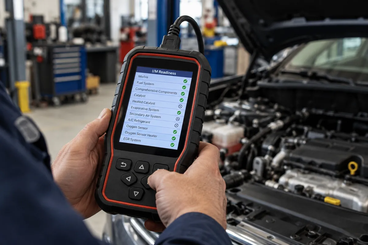
Oxygen sensor replacement: The O2 sensor monitor and O2 sensor heater monitor must complete after replacement. The heater monitor is the easier of the two: it runs on any key-on cycle once the engine has started and confirms the heater element is drawing its expected current (typically 0.5-2A depending on sensor design). The heater monitor typically shows “complete” after 5-10 minutes of engine operation. The O2 sensor response test (the main sensor performance monitor) requires a drive cycle with a cold start, warm-up, steady-state cruise, and deceleration. After the monitor completes, check Mode 01 readiness (confirm O2 sensor monitor = complete) and Mode 06 response time TIDs: a new OEM-quality sensor should show response times at 20-40% of the maximum allowed limit. A response time at 75-90% of the limit on a freshly installed sensor suggests an aftermarket sensor with substandard performance or an incorrect part number.
For a professional-grade tool, my top pro-level scanners covers the top options.
Catalytic converter replacement: The catalyst monitor is the primary verification and requires the most demanding drive cycle of any common repair. The catalyst monitor enables only when: coolant temperature is above operating threshold, engine has been at stable idle for at least 90 seconds, vehicle has accelerated to at least 55 mph, maintained steady cruise for 3 or more minutes, followed by a specific deceleration. Most converter replacements require 1-3 complete drive cycle attempts before the catalyst monitor shows “complete.” After completion, the Mode 06 catalyst efficiency result (TID 0x21 for bank 1) should show the measured value significantly above the minimum limit. A quality OEM-specification converter typically produces a Mode 06 efficiency value of 0.92-0.97 against a minimum limit of 0.75-0.82 (exact values vary by calibration). If the Mode 06 result shows the new converter barely above the minimum limit (e.g., 0.81 against a 0.80 minimum), the converter specification may be incorrect for the vehicle or the converter may be a low-quality unit that will fail the monitor within months.
If you are on a tight budget, my top budget scanner picks covers the top value picks.
EVAP component replacement (purge valve, vent valve, canister, gas cap): The EVAP monitor is the most demanding to complete. It requires: the vehicle to have sat for a defined period at appropriate ambient temperature (typically 40-95°F, between 4-35°C), a cold start (ECT below 86°F/30°C at startup on many calibrations), and a specific drive pattern including an initial warm-up phase and a cruise phase. The EVAP monitor can take 2-5 days of normal driving before it completes after a component replacement. A gas cap replacement is the easiest EVAP repair to verify: if P0457 or P0456 was caused by a loose or defective cap and the new cap seals correctly, the EVAP monitor will complete and the code will not return. If the code returns after the cap is replaced, the EVAP leak is elsewhere in the system. EVAP repairs are best confirmed by a smoke test after code clearing to visually confirm the seal before relying on the monitor to verify.
My my guide on perform evap system test covers this step by step.
Ford F-150 owners can find the right scanner in my best scanners for the F-150.
EGR component replacement: The EGR monitor must complete to verify the repair. Check Mode 06 EGR test results if available to confirm the EGR valve is flowing within specification. A common mistake after EGR cleaning or replacement: carbon buildup in the EGR passage downstream of the valve that the repair did not address. The EGR valve opens correctly, but flow is restricted by carbon in the passage. Mode 06 EGR flow data (measured flow rate versus commanded flow rate) reveals this: a correct valve with restricted passages shows lower measured flow than commanded, similar to the pre-repair condition.
My obd2 mode 06 explained monitor test results covers this step by step.
Audi Q8 owners can find the right scanner in my best scanners for the Q8.
Mass air flow sensor replacement: The MAF sensor is monitored by the comprehensive component monitor, a continuous monitor that runs on every drive cycle. After replacing a MAF sensor, the comprehensive component monitor validates the new sensor’s signal within the first drive at operating temperature. Verify by reading Mode 01 live data: at idle (warmed up), MAF output in g/s should be appropriate for the engine displacement (approximately 1.5-3 g/s per liter of displacement at idle is a rough guide). At steady 65 mph cruise, MAF output should be proportional to engine load. Long-term fuel trim should begin trending toward zero over subsequent drive cycles if the MAF was the cause of the original lean/rich condition. A LTFT that does not move toward zero after MAF replacement may indicate additional contributing faults (vacuum leak, injector variation).
My my guide on diagnose vacuum leaks covers this step by step.
My my guide on read maf sensor data covers this step by step.
Audi owners looking for the right scanner should check my top-rated scanners for Audi.
Misfire repairs (coil, plug, injector): The misfire monitor is continuous. After replacing a failing ignition coil, spark plug, or injector, the misfire monitor updates on the next drive cycle. Verify by reading Mode 01 live data during a test drive at the RPM and load where the misfire was originally detected: misfire counts in the PID data should be zero or minimal. A rolling misfire counter that increments during the test drive after the repair indicates the repair did not resolve the misfire for that cylinder. Check the specific cylinder’s misfire count PID if your scanner supports individual cylinder misfire data.
My how to read live data for misfire diagnosis covers this step by step.
My what are obd2 pids and how do they work covers this step by step.
My my guide on diagnose misfires covers this step by step.
Honda owners looking for the right scanner should check my top-rated scanners for Honda.
Diagnosing a Repair That Did Not Fix the Code
A code that returns within the same drive cycle as the repair almost always indicates misdiagnosis rather than a defective replacement part. The most common misdiagnosis pattern in OBD2 repair: treating a symptom code as a cause code. P0171 (fuel system lean, bank 1) describes a symptom — the engine is running lean. It does not tell you why. Replacing the upstream oxygen sensor because the freeze frame showed high STFT and the O2 sensor was old may not fix P0171 if the actual cause is a vacuum leak that the new O2 sensor is now accurately reporting. The code returns because the lean condition still exists.
BMW owners looking for the right scanner should check my top-rated scanners for BMW.
The correct post-misdiagnosis approach: do not replace additional components speculatively. Return to live data diagnosis with the new baseline established after the first repair. Read STFT and LTFT at idle and compare to STFT and LTFT at cruise: if STFT is high at idle (-15% to +20%) but closer to zero at cruise, the lean condition is load-dependent (manifold vacuum leak signature — more prominent at high vacuum/idle conditions). If STFT is high at both idle and cruise, the lean condition is consistent across loads (MAF sensor reading low, fuel delivery issue, or a large leak affecting all loads).
I cover this capability in more detail in my Innova 3100RS breakdown.
A specific diagnostic technique for vacuum leak identification after P0171 with high STFT at idle: use propane enrichment or brake cleaner spray (carefully, away from ignition sources) around intake manifold gaskets, throttle body gasket, PCV hose connections, and vacuum hose connections while watching STFT in Mode 01 live data. When propane or enriching spray enters a vacuum leak, STFT drops briefly and then returns high when the spray stops. This identifies the exact leak location without disassembly. For a more controlled method, a smoke machine injecting inert smoke into the intake manifold under slight pressure reveals leaks visually.
I cover this capability in more detail in my BlueDriver Pro breakdown.
Code return after EVAP repairs specifically: EVAP system P0455 (large leak) or P0456 (small leak) codes can return even after replacing the suspected component if the actual leak is elsewhere. EVAP systems on modern vehicles have multiple potential leak points: fuel filler cap, fuel filler neck, EVAP canister, purge valve, vent valve, fuel tank pressure sensor fitting, vapor hose connections, and on turbocharged engines, additional boost-related EVAP connections. Replacing a purge valve that is not leaking while the actual leak is at a cracked vapor hose returns the code reliably. A smoke test of the EVAP system is the correct diagnostic step before any EVAP component replacement: it reveals which specific component or connection is leaking rather than replacing components by guess.
I explain this in more detail in my can you drive with check engine light on.
Using Mode 06 for Quantitative Repair Verification
Mode 01 readiness status provides binary confirmation: a monitor ran and passed. Mode 06 provides quantitative confirmation: a monitor ran and passed with this specific measured value at this margin above or below the threshold. For expensive repairs, quantitative confirmation is worth the extra step.
I explain this in more detail in my check engine light on but no codes stored.
After catalyst replacement, Mode 06 TID 0x21 shows the efficiency value. The interpretation framework: a value more than 15% above the minimum limit (e.g., 0.92 against 0.80 minimum) confirms a quality, correctly specified converter with substantial service life ahead. A value 5-8% above the minimum (e.g., 0.85 against 0.80) passes the test but suggests a marginal converter — either a lower-quality aftermarket unit or possibly incorrect specification for the vehicle. Values this close to the minimum warrant investigating whether the correct OEM-equivalent converter was used. If the shop installed a cheap generic universal converter rather than a properly catalyzed vehicle-specific unit, Mode 06 reveals the underperformance immediately rather than waiting for P0420 to return in 6 months.
I explain this in more detail in my my guide on check used car.
After O2 sensor replacement, Mode 06 response time TIDs (0x01, 0x02 for bank 1 sensor 1) confirm sensor quality. A new OEM-equivalent sensor should show response time at approximately 20-35% of the maximum allowed limit. Response time at 60-70% of the maximum limit on a brand-new sensor indicates a low-quality aftermarket sensor with degraded performance — it passes the test now but will likely approach the failure threshold within 18-24 months rather than the 5+ year service life of a quality sensor.
I explain this in more detail in my check engine light came back after clearing codes.
How Long to Wait Before Concluding the Repair Held
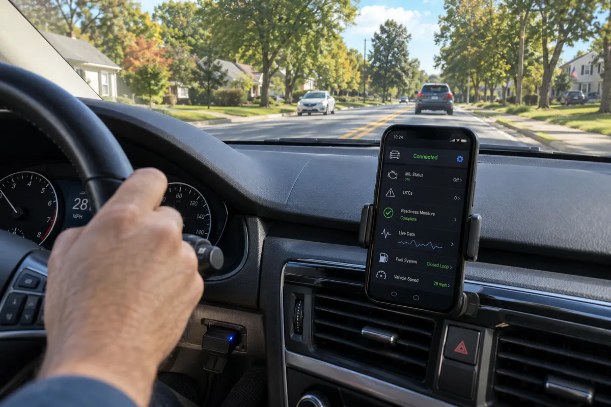
The minimum verification period is defined by the slowest monitor associated with the repaired system. For continuous monitors (misfire, fuel system, comprehensive component), one complete drive cycle — a cold start through a full warm-up and 15-20 minutes of mixed driving — is sufficient to confirm the repair resolved a persistent fault. If the code has not returned after one warm drive cycle and the relevant live data parameters are normal, the repair is confirmed for continuously monitored systems.
Ford owners looking for the right scanner should check my scanner recommendations for Ford owners.
For non-continuous monitors (catalyst, EVAP, O2 sensor, EGR), the monitor must complete at least once and show “complete” in Mode 01. For the EVAP monitor, which requires a cold soak and specific cold-start sequence, the minimum verification period is 2-3 days of normal driving that includes at least two cold starts (engine fully cooled before startup) and at least one drive that satisfies the EVAP monitor’s enabling conditions. For intermittent faults that occurred only under specific conditions, the repair can only be confirmed by operating the vehicle under those specific conditions and verifying the fault does not recur.
Permanent codes (Mode 0A) have the most stringent confirmation requirement: the code clears only when the ECM has run the associated monitor and passed it on three consecutive drive cycles after the repair. Until the ECM confirms three passes, the permanent code remains stored and the check engine light stays on. This is by design: permanent codes were specifically introduced to prevent code-clearing shortcuts. After an EVAP repair with a permanent P0456, expect the check engine light to stay on for 3-5 days of normal driving as the ECM runs and passes the EVAP monitor three times to confirm the repair.
Chevy owners looking for the right scanner should check my top-rated scanners for Chevy.
FAQs
The workshop cleared my codes without driving the car after the repair. Is the repair verified?
No. Clearing codes resets monitors to incomplete and removes the evidence of the fault, but does not verify the repair worked. A cleared code means the ECM has no memory of the fault — it does not mean the fault is gone. Verification requires driving the vehicle until the associated monitor completes and confirms no code returned. A workshop that clears codes and returns the vehicle without performing a post-repair drive cycle has not verified anything: they have confirmed the light was off at the moment of code clear. Request that the workshop perform a drive cycle appropriate to the repaired system and rescan the vehicle before handing it back. Many quality shops include a “road test with scanner monitoring” as standard procedure precisely because verification of the repair is part of the diagnostic service, not optional.
Can a code not return for weeks and then suddenly come back?
Yes, and this is one of the most common post-repair complaint patterns. Non-continuous monitors require specific enabling conditions that may not occur in every drive. An EVAP monitor may not run for weeks if the vehicle is only operated in short city trips that never satisfy the cold-start sequence. A catalyst monitor may not run on a vehicle that is only driven in traffic-heavy city conditions where the 3+ minutes of steady 55 mph cruise required for the catalyst test never occurs. During this period, the monitor status shows “incomplete” — the monitor has not run yet. When conditions finally align (a highway drive on a cool morning with appropriate fuel level) and the monitor runs, if the original fault is still present, the code stores. The owner experiences this as “the repair seemed to work for weeks, then the code came back.” The repair did not work; the monitor just had not run yet to confirm it did not work.
What if I cannot get the monitor to complete to verify the repair?
A monitor that will not complete after multiple proper drive cycle attempts is diagnostic information on its own. The monitor has enabling conditions that it is not meeting, which usually means either a related fault is blocking the monitor from running or the monitored system has a marginal condition the monitor is detecting before it commits to a pass or fail result. Check Mode 01 for any pending codes (faults detected but not yet confirmed enough times to become stored codes): a pending code may explain why the monitor will not complete by indicating the monitored system has an active issue the ECM cannot yet classify as a definite pass or fail. For EVAP monitors specifically, check that the fuel tank level is between 15% and 85% (EVAP monitor enabling condition on most vehicles), ambient temperature is in the acceptable range (typically above 40°F/4°C), and the vehicle has been parked overnight before the cold-start attempt. If all enabling conditions are met and the monitor still will not complete, the EVAP system has a condition the monitor is detecting as problematic even though it is not severe enough to have stored a code yet.
Should I verify the repair at the mechanic’s shop or is it enough to check at home?
Checking at home with your own scanner is perfectly valid and in some ways preferable because you control the timing and can check immediately after the relevant drive cycle completes, without waiting for a shop appointment. The key requirement is that your scanner can read Mode 01 readiness status to confirm monitor completion and, ideally, Mode 06 for quantitative verification on catalyst or O2 sensor repairs. A basic OBD2 emissions code reader shows readiness status on any scanner sold since 2000. Mode 06 capability requires a mid-range or better scanner. If you have only a basic reader that shows pass/fail readiness status, readiness confirmation is sufficient for most repairs — Mode 06 is the extra step for high-value repairs where component quality matters.