
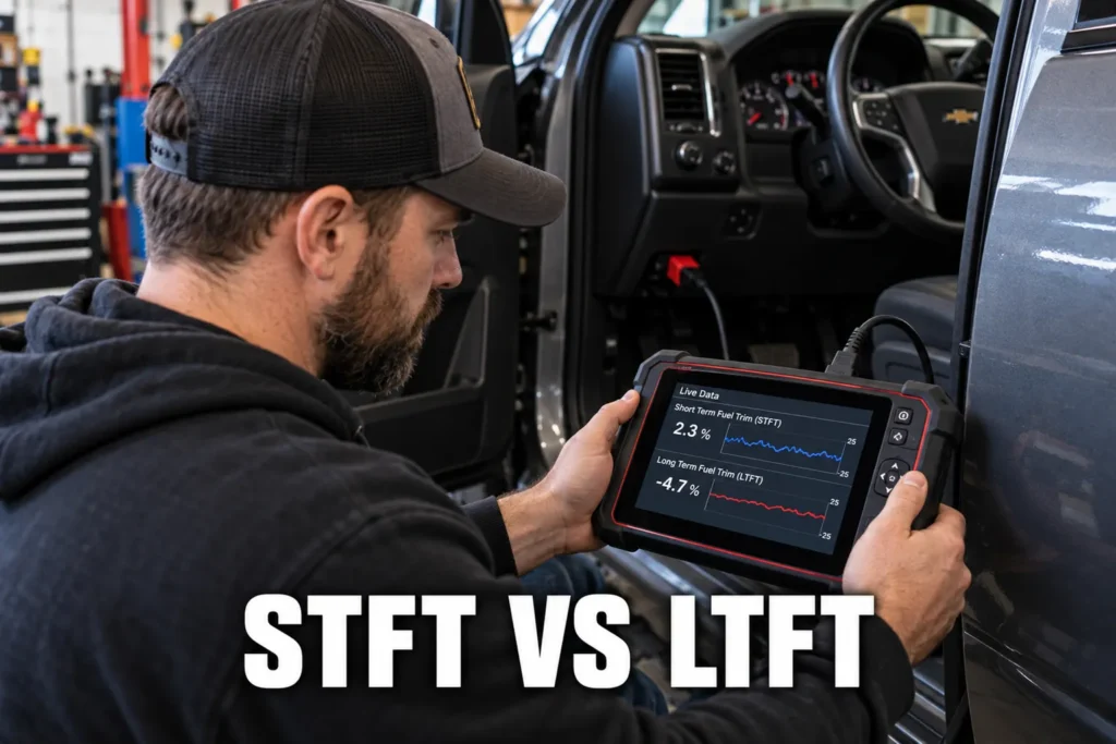
STFT vs LTFT: How to Read Fuel Trims on an OBD2 Scanner
By Kamil Siegień / October 12, 2026
Fuel trim is the ECM’s real-time record of how much it is adjusting its commanded fuel delivery from the calculated base. A fuel trim at zero means the engine is getting exactly the fuel amount the ECM calculated it needs. A positive fuel trim means the ECM is adding fuel (the mixture is running lean and the O2 sensor is demanding more). A negative fuel trim means the ECM is subtracting fuel (the mixture is running rich and the O2 sensor is demanding less). Reading fuel trim correctly and understanding the difference between short-term and long-term trims is one of the most powerful diagnostic skills available through a standard OBD2 scanner, applicable to lean, rich, vacuum leak, MAF, and injector faults without any additional tools beyond the scanner itself.
Nissan owners looking for the right scanner should check my best diagnostic tools for Nissan.

About the author: Hello! I’m Kamil Siegień, founder of OBD2 Scout. My diagnostic experience started with an engine rebuild on a 2014 Skoda Superb 1.8 TSI, where tuning from 160 to 222 hp required mastering live data and ECU behavior that basic code readers cannot handle. I am a former BMW and MINI employee and regularly use diagnostic scanners on my own Audi A4 2.0 TFSI.
This guide covers what STFT and LTFT measure and how they relate to each other, what the normal ranges are and when values indicate a fault, how to read fuel trims at idle versus under load to identify vacuum leaks versus MAF faults, how bank-specific fuel trims identify which bank has a problem, and how to combine fuel trim data with O2 sensor readings for complete fuel system diagnosis.
My my guide on diagnose vacuum leaks covers this step by step.
I cover this capability in more detail in my Innova 3100RS deep dive.
For scanner recommendations to perform this type of work, see my best diagnostic scanners.
What STFT and LTFT Measure
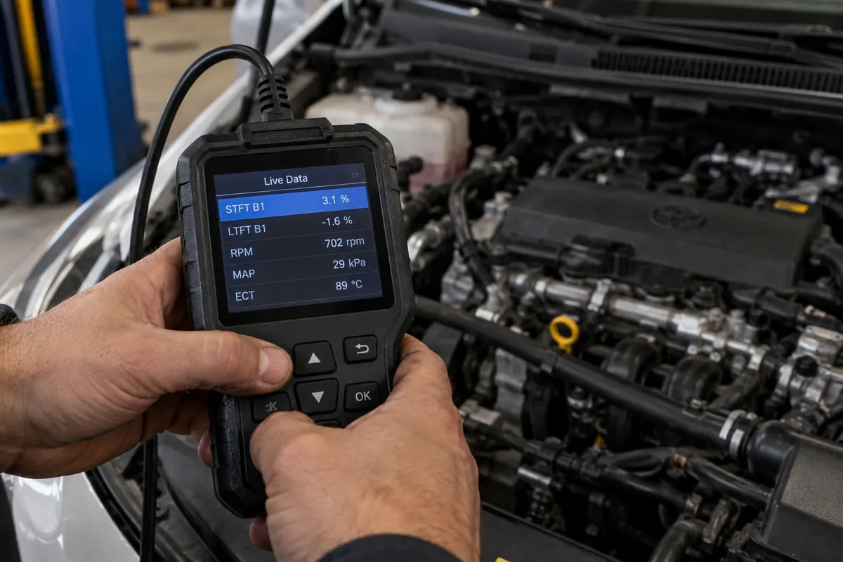
Short-term fuel trim (STFT) is the ECM’s immediate, real-time adjustment to fuel delivery based on the upstream oxygen sensor’s current signal. The O2 sensor alternates between high voltage (rich mixture, above 0.6 V) and low voltage (lean mixture, below 0.3 V) in a closed-loop switching pattern. When the sensor shows lean (low voltage), the ECM increases fuel delivery immediately: STFT goes positive. When the sensor shows rich (high voltage), the ECM reduces fuel delivery: STFT goes negative. This adjustment happens continuously, multiple times per second, and STFT oscillates between positive and negative values in a healthy system with a functioning O2 sensor.
I explain this in more detail in my my guide on use an.
Audi owners looking for the right scanner should check my best diagnostic tools for Audi.
Long-term fuel trim (LTFT) is the ECM’s learned average of the STFT corrections over many drive cycles. If the engine consistently needs more fuel (STFT is consistently positive over time), the ECM shifts the LTFT in the positive direction to incorporate this learned correction into the base fuel calculation, reducing the burden on STFT. LTFT changes slowly: it responds to trends over hours and days of driving rather than seconds. LTFT represents the ECM’s best estimate of the systematic error in its base fuel calculation, adjusted for the specific engine’s condition at this point in its life.
I explain this in more detail in my can you drive with check engine light on.
For a professional-grade tool, my best shop-grade diagnostic tools covers the top options.
The combined effect of STFT and LTFT is the total fuel correction: what you care about diagnostically is their sum. If LTFT is positive 8 percent and STFT is oscillating around positive 2 percent, the total correction is approximately 10 percent additional fuel being added, which indicates a lean condition the ECM is compensating for. Scanners that display both values allow you to read both simultaneously and calculate the sum.
Honda owners looking for the right scanner should check my best diagnostic tools for Honda.
Normal and Abnormal Fuel Trim Values
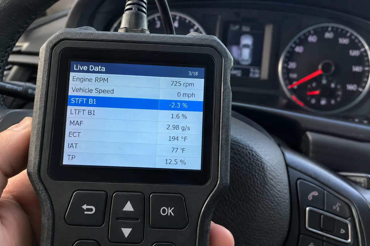
Healthy fuel trim values at warm idle on a properly functioning engine: STFT oscillates between approximately negative 5 and positive 5 percent, with an average near zero. LTFT sits between negative 5 and positive 5 percent. Both STFT and LTFT within this range indicate the ECM’s fuel calculations are close to correct and the fuel control system is operating within its normal compensation range.
I explain this in more detail in my how to diagnose vacuum leaks with obd2 scanner.
If you are on a tight budget, my top entry-level code readers covers the top value picks.
Fuel trims between positive or negative 5 and 10 percent indicate a minor lean or rich condition. The ECM is compensating, the system is still in closed-loop control, but the deviation from zero suggests a developing fault or a minor calibration drift. Trims consistently above positive 10 percent (LTFT, or STFT + LTFT combined) indicate a significant lean condition: the ECM is adding substantial extra fuel to maintain the target mixture. This range is where fault codes for lean system (P0171 bank 1, P0174 bank 2) are typically triggered. Trims above positive 20 to 25 percent indicate a severe lean condition where the ECM may be approaching the limit of its compensation range.
I explain this in more detail in my my guide on check used car.
If you prefer a wireless setup, my top wireless scanner picks covers the best options.
Consistently negative fuel trims (negative 10 percent or more for LTFT) indicate a rich condition. This is less common as a sensor-reading fault and more commonly caused by a leaking fuel injector (continuously dripping fuel even when not commanded), a stuck-open purge valve continuously routing raw fuel vapor to the intake, or an excessively high fuel pressure from a failed fuel pressure regulator. Negative fuel trims combined with rich-running symptoms (black smoke, fuel smell, rich O2 sensor readings) confirm the rich condition diagnostic direction.
My my guide on reset injector coding covers this step by step.
BMW owners looking for the right scanner should check my best diagnostic tools for BMW.
Idle Fuel Trims vs Load Fuel Trims for Vacuum Leak vs MAF Diagnosis
The behavior of fuel trims at idle versus at load is one of the most diagnostically powerful patterns available from standard OBD2 data. A vacuum leak and a failing MAF sensor both produce positive fuel trims (lean condition), but they behave differently across the RPM and load range:
Honda CR-V owners can find the right scanner in my CR-V-compatible diagnostic tools.
Vacuum leak signature: positive fuel trims at idle that decrease significantly or normalize at mid-load and highway cruise. A vacuum leak introduces unmetered air at idle when the intake manifold vacuum is high (30+ inHg). At higher RPM and load, manifold vacuum decreases substantially, and the same vacuum leak introduces proportionally less additional air relative to the total airflow. The fuel trim improves at load because the unmetered air is a smaller fraction of total airflow. If your LTFT is positive 15 percent at idle and drops to near zero at 2,500 RPM under steady load, a vacuum leak is the likely cause.
Ford owners looking for the right scanner should check my scanner recommendations for Ford owners.
MAF sensor under-reading signature: positive fuel trims that are similar or worsen at mid-load compared to idle. A MAF sensor that under-reports airflow causes the ECM to under-calculate the required fuel at all load conditions. Unlike a vacuum leak (which adds air only at high vacuum), a MAF error scales with engine airflow: the more air the engine ingests, the larger the absolute fuel delivery error. If your LTFT is positive 15 percent at idle and remains at positive 12 to 15 percent at highway cruise, the MAF sensor is the more likely cause than a vacuum leak.
Chevy owners looking for the right scanner should check my best diagnostic tools for Chevy.
Bank-Specific Fuel Trims

On V6 and V8 engines with two separate cylinder banks, the ECM maintains separate fuel trim values for each bank (Bank 1 and Bank 2). Bank 1 is conventionally the bank containing cylinder 1 (and on most longitudinal engine layouts, the bank nearest the firewall). Bank 2 is the opposite bank. The location of Bank 1 varies by engine orientation and manufacturer.
Ford F-150 owners can find the right scanner in my top diagnostic tools for the F-150.
When both banks show similar positive or negative fuel trims, the root cause is a component that affects both banks equally: fuel pressure (applies to all cylinders), intake manifold vacuum leak at a shared plenum, MAF sensor (reads total airflow for the whole engine), or catalytic converter efficiency (which affects O2 sensor feedback on both banks). When only one bank shows significant positive or negative fuel trim while the other is near zero, the cause is bank-specific: a vacuum leak on one intake manifold bank, a failing O2 sensor on one bank, a fuel injector issue affecting only cylinders on one bank, or a catalyst efficiency issue on one bank.
My my guide on test catalytic converter covers this step by step.
Audi Q8 owners can find the right scanner in my Q8-compatible diagnostic tools.
Combining Fuel Trims with O2 Sensor Data
Fuel trims are derived from O2 sensor feedback. Reading the O2 sensor voltage alongside the fuel trims confirms the direction of the fuel control response. At steady idle in closed-loop, the upstream O2 sensor should switch between high (rich, above 0.6 V) and low (lean, below 0.3 V) at a rate of approximately 1 to 3 times per second on a healthy engine. A sensor that switches but stays predominantly on the lean side (more time below 0.3 V than above 0.6 V) explains a positive STFT: the ECM is adding fuel because the sensor is reading lean most of the time.
Toyota owners looking for the right scanner should check my best diagnostic tools for Toyota.
A downstream O2 sensor (after the catalyst) should show a stable, relatively high voltage (approximately 0.6 to 0.8 V, with minimal switching) if the catalyst is functioning. If the downstream sensor mimics the upstream sensor’s switching pattern, catalyst efficiency has dropped and a P0420/P0430 fault is developing. This downstream sensor behavior is separate from the fuel trim calculation but should be checked alongside fuel trims on any vehicle with fuel-related fault codes to confirm the catalyst status is not contributing to an O2 sensor response that looks like a lean fault.
I cover this capability in more detail in my BlueDriver diagnostic coverage.
FAQs
What is the acceptable fuel trim range before a code is stored?
Most ECMs store a P0171 (system lean bank 1) or P0174 (system lean bank 2) code when the LTFT exceeds approximately positive 10 to 15 percent at idle (the specific threshold varies by manufacturer and software calibration). Some manufacturers trigger the code based on LTFT alone, others use the combined STFT + LTFT sum. The fault requires confirmation on two consecutive drive cycles in most systems before the code is stored. Fuel trims in the 10 to 12 percent range may be approaching the threshold without having stored a code yet, which is why checking fuel trims even in the absence of a check engine light is valuable for identifying developing lean conditions.
Why does STFT oscillate but LTFT stays fixed?
STFT oscillates because it responds in real time to the O2 sensor’s rapid rich-lean switching. LTFT changes slowly because it accumulates the trend over many minutes and drive cycles. In a healthy system, STFT oscillates around zero while LTFT represents the long-term baseline correction. If LTFT is positive 8 percent, STFT oscillates around zero to slightly positive because the LTFT correction has already incorporated the chronic lean offset, leaving only the random short-term variation for STFT to manage. This is normal and expected: a system with LTFT at positive 8 percent and STFT near zero is compensating for a persistent lean condition using LTFT.
Can I diagnose a vacuum leak with fuel trim data alone?
You can identify that a lean condition exists and that it is likely a vacuum leak (positive fuel trims at idle that decrease under load), but you cannot identify the specific leak location from fuel trim data alone. Confirming the vacuum leak location requires either a smoke test (pressurizing the intake system with smoke and observing where it exits), listening with a mechanic’s stethoscope or a hose near suspected vacuum hose connections, or spraying carburetor cleaner near suspected areas (which causes a momentary RPM change when it enters a vacuum leak, though this method carries a fire risk and should be used carefully). Fuel trim data directs you to suspect a vacuum leak; additional physical testing finds the specific location.
My fuel trim is positive at idle but the O2 sensor shows rich. What does this mean?
A positive fuel trim (ECM adding fuel because it thinks the mixture is lean) alongside a rich O2 sensor reading indicates the O2 sensor may be biased to read rich when it should read lean. A contaminated O2 sensor electrode (contaminated with silicon from a silicone sealant used during an intake manifold repair, or with phosphorus from burning engine oil) can bias the sensor output toward a higher voltage reading, causing the ECM to see a rich signal when the actual mixture is lean. This condition produces a paradox: the ECM adds fuel (positive trim) but the sensor shows rich anyway because the sensor itself is giving an incorrect reading. Replacing the upstream O2 sensor and observing whether the fuel trim normalizes confirms a biased sensor.