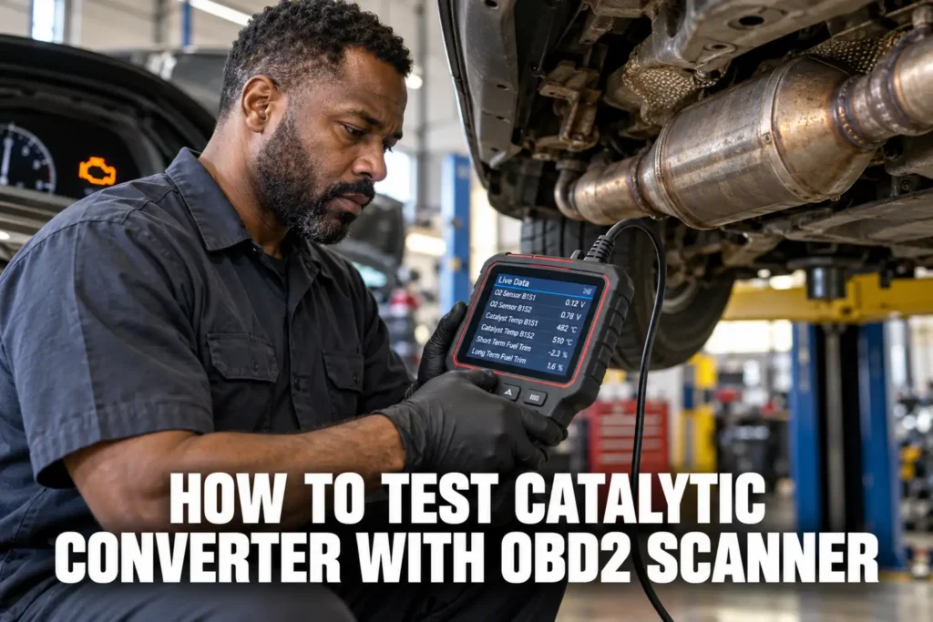
How to Test a Catalytic Converter with an OBD2 Scanner: Live Data and Mode 6 Methods
By Kamil Siegień / October 12, 2026
A catalytic converter test using an OBD2 scanner does not involve removing the converter or using exhaust gas analyzers. The scanner reads the downstream oxygen sensor signal alongside the upstream signal, and the ratio of their activity tells you whether the catalyst is still converting exhaust gases effectively. A working catalyst produces a stable downstream sensor reading. A failing catalyst produces a downstream sensor that mirrors the upstream sensor’s switching pattern.
My my guide on test o2 sensor covers this step by step.
If you prefer a wireless setup, my top wireless scanner picks covers the best options.

About the author: Hello! I’m Kamil Siegień, founder of OBD2 Scout. My diagnostic experience started with an engine rebuild on a 2014 Skoda Superb 1.8 TSI, where tuning from 160 to 222 hp required mastering live data and ECU behavior that basic code readers cannot handle. I am a former BMW and MINI employee and regularly use diagnostic scanners on my own Audi A4 2.0 TFSI.
This guide covers the chemistry behind the catalyst efficiency test, how the ECU runs the catalyst monitor, what normal versus failing catalyst live data looks like, how to use Mode 6 to read the ECU’s own test results, which DTCs relate to catalyst efficiency, and what to do when a P0420 or P0430 code appears alongside a passing upstream O2 sensor.
My obd2 mode 06 explained monitor test results covers this step by step.
My my guide on obd2 mode 6 explained use for diagnosis covers this step by step.
iPhone users looking for a compatible scanner can check my top iPhone-compatible scanners.
What the Catalytic Converter Does and How the ECU Tests It
The catalytic converter reduces three pollutants: hydrocarbons (HC), carbon monoxide (CO), and nitrogen oxides (NOx). The oxidation catalyst handles HC and CO by adding oxygen to them, converting them to carbon dioxide and water. The reduction catalyst handles NOx by removing oxygen, converting nitrogen oxides to nitrogen and oxygen. Modern three-way catalysts do both reactions simultaneously over a palladium, platinum, and rhodium substrate.
Audi owners looking for the right scanner should check my top-rated scanners for Audi.
The catalyst stores oxygen during lean combustion phases and releases it during rich combustion phases. This oxygen storage capacity (OSC) is what makes the catalyst effective: it buffers the fluctuating exhaust composition from the engine and provides a stable, averaged environment for the chemical conversion reactions. As the catalyst ages, the precious metal substrate degrades, the OSC decreases, and the catalyst passes more unprocessed exhaust gases downstream.
Mercedes owners looking for the right scanner should check my top-rated scanners for Mercedes.
The ECU tests catalyst efficiency by comparing the downstream O2 sensor signal to the upstream signal. A catalyst with sufficient OSC smooths the oxygen pulses before they reach the downstream sensor, so the downstream sensor sees a stable reading. When the OSC is depleted, the oxygen pulses pass through unprocessed and the downstream sensor switches at nearly the same rate as the upstream sensor. The ECU quantifies this by measuring how many times the downstream sensor crosses the midpoint voltage per upstream sensor crossing. A ratio close to 1.0 (equal crossing rates) means the catalyst has failed its efficiency threshold.
Honda CR-V owners can find the right scanner in my top CR-V diagnostic tools.
Setting Up the Live Data Test
Connect your scanner to the OBD2 port and navigate to Mode 1 live data. Select these PIDs at minimum: O2S11 (Bank 1 Sensor 1, upstream), O2S12 (Bank 1 Sensor 2, downstream), short-term fuel trim Bank 1 (STFT11), long-term fuel trim Bank 1 (LTFT11), and coolant temperature. On V6/V8 engines, add Bank 2 equivalents: O2S21, O2S22, STFT21, LTFT21.
My a pid obd2 diagnostics explained covers this step by step.
My my guide on diagnose vacuum leaks covers this step by step.
My my guide on stft vs ltft read fuel trims covers this step by step.
My obd2 modes explained modes 1 through 10 covers this step by step.
The test requires fully warmed engine at normal operating temperature. The catalyst monitor specifically needs the catalyst itself to reach operating temperature, which takes longer than just the coolant reaching normal temperature. The catalyst operating temperature is between 400°C and 800°C (750°F to 1,470°F). Plan for at least 15 minutes of driving before the test to ensure the catalyst is fully up to temperature. A catalyst that has not fully warmed up shows more switching activity on the downstream sensor than it would at full operating temperature, which can produce false readings suggesting catalyst failure.
Ford F-150 owners can find the right scanner in my F-150-compatible diagnostic tools.
If your scanner supports graphing mode, enable it for both the upstream and downstream sensor PIDs. The visual comparison between the two waveforms is the clearest way to assess catalyst condition. Set the graph Y-axis to 0 to 1.3 volts and time scale to 30 to 60 seconds to capture enough switching cycles for comparison.
Audi Q8 owners can find the right scanner in my best scanners for the Q8.
What Normal Catalyst Live Data Looks Like
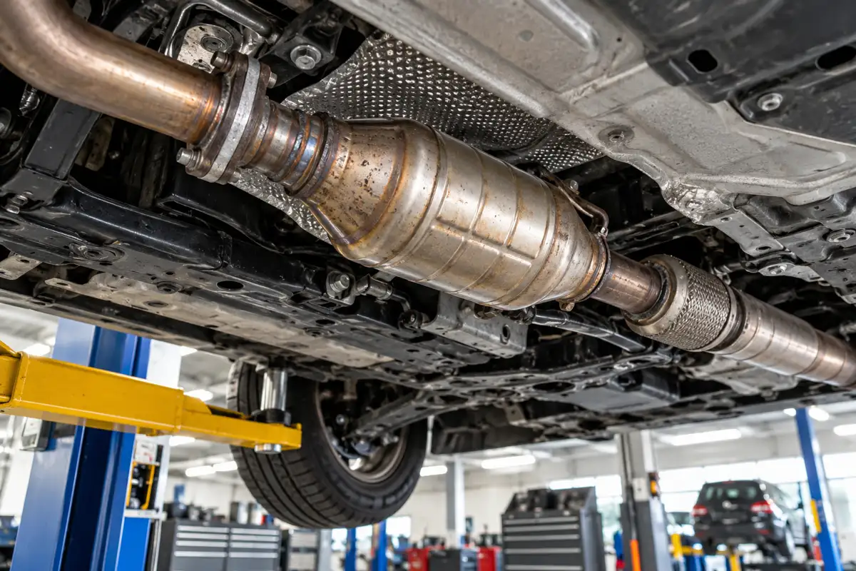
In a vehicle with a healthy catalyst, the upstream sensor (Bank 1 Sensor 1) switches actively between approximately 0.1 and 0.9 volts at roughly 0.5 to 2 cycles per second at steady warm idle. Meanwhile, the downstream sensor (Bank 1 Sensor 2) shows a slow, gently undulating signal centered around 0.5 to 0.7 volts with minor variation. The downstream trace does not mirror the upstream trace. It barely moves by comparison.
I cover this capability in more detail in my BlueDriver diagnostic coverage.
The downstream sensor’s stability reflects the catalyst’s OSC. Every time the upstream sensor signals lean (low voltage), the catalyst releases stored oxygen to continue conversion. Every time the upstream sensor signals rich (high voltage), the catalyst absorbs the excess oxygen. The downstream sensor sits behind that oxygen buffer and sees nearly constant composition. Its voltage only drifts slowly as the catalyst reaches its storage limits and briefly passes through gases that are slightly more lean or rich than averaged.
I cover this capability in more detail in my OBDLink MX+ coverage.
A voltage range of 0.1 to 0.9 volts on the downstream sensor, switching at a rate comparable to the upstream sensor, indicates a failed catalyst. The OSC is gone. The exhaust pulses pass through unchanged. The downstream sensor detects the same alternating lean and rich exhaust that the upstream sensor detects. The ECU’s catalyst monitor detects this by computing a switching ratio: how often the downstream sensor crosses 0.45 volts per upstream sensor crossing. A healthy ratio is below 0.2 (downstream switches less than 20% as often as upstream). A failing ratio is above 0.7 to 0.9 depending on the manufacturer’s threshold.
I explain this in more detail in my can you drive with check engine light on.
How to Count Switching Cycles in Live Data
If your scanner does not display a graph, count switch crossings manually in the numerical live data display. Watch the upstream sensor value for 30 seconds and count each time it crosses from above 0.45 V to below 0.45 V (or vice versa). Then watch the downstream sensor for 30 seconds and count the same crossings. Divide the downstream crossing count by the upstream crossing count. A healthy ratio is 0.1 to 0.2. A failing ratio is 0.7 or higher.
This counting method works at stable idle but becomes harder during driving. At higher RPM and load, both sensors switch faster, and manual counting is impractical. Graphing mode or Mode 6 data (which automates the measurement) is more reliable for on-road testing. However, the idle test at full operating temperature is sufficient to identify a clearly failed catalyst. A borderline catalyst may show a passing ratio at idle but a failing ratio at highway speed, which is why the ECU’s catalyst monitor specifically runs at 55 to 65 mph for several minutes.
I explain this in more detail in my my guide on check used car.
Mode 6 Catalyst Efficiency Test Results
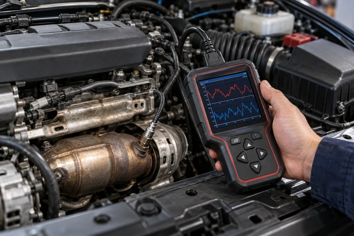
Mode 6 on OBD2-compliant vehicles includes the results of the ECU’s own catalyst monitor test. The ECU runs this test under specific enabling conditions during normal driving, calculates the catalyst efficiency ratio using its own algorithm, and stores the result in the Mode 6 data area accessible through the scanner. The Mode 6 result provides the measured efficiency value alongside the minimum acceptable threshold, giving you a precise number rather than just a pass/fail indicator.
I explain this in more detail in my my guide on use an.
To access Mode 6 catalyst data: on your scanner, navigate to the OBD2 mode menu or special tests and select Mode 6 or On-Board Monitor Test. Select the catalyst efficiency test (the Test ID varies by manufacturer; on most GM vehicles it is TID $01 CID $21; on most Ford vehicles it is TID $01 CID $0B; check your specific make). The result shows the measured switching amplitude or ratio, the minimum threshold, and a pass or fail.
I explain this in more detail in my does obd2 work on electric cars.
A Mode 6 catalyst result is more reliable than the manual live data observation because the ECU collects it under a controlled driving condition at specific load and speed. A catalyst that appears borderline at idle may clearly fail the Mode 6 result because the ECU’s test runs at a more demanding operating point. Conversely, a catalyst showing borderline switching at idle may still pass Mode 6 if the test was collected during easier conditions. If Mode 6 shows a fail or a value close to the minimum threshold, the catalyst is degraded even if no P0420 DTC has confirmed yet.
Honda owners looking for the right scanner should check my top-rated scanners for Honda.
When P0420 or P0430 Appears
P0420 (Catalyst System Efficiency Below Threshold, Bank 1) and P0430 (Bank 2) are stored after the ECU’s catalyst monitor runs and produces a failing result on the second consecutive drive cycle where the monitor ran. The presence of either code confirms the ECU has tested the catalyst twice under the required enabling conditions and found efficiency below its minimum threshold both times.
BMW owners looking for the right scanner should check my top-rated scanners for BMW.
Before replacing the catalytic converter, verify the upstream O2 sensor is working correctly. A slow or lazy upstream sensor produces fuel trim swings that affect how the downstream sensor responds, and can produce a P0420 code on a healthy catalyst. Check upstream sensor switching rate, fuel trim values, and Mode 6 O2 sensor response test results before concluding the catalyst is the cause.
My my guide on read o2 sensor live data covers this step by step.
For scanner recommendations to perform this type of work, see my top OBD2 scanner picks.
Exhaust leaks between the catalytic converter and the downstream sensor also cause P0420. An exhaust leak dilutes the downstream sensor reading with fresh air, making the sensor read lean regardless of catalyst condition. The downstream sensor voltage drops toward 0.1 volts and stays there rather than showing switching activity. Inspect the exhaust system between the converter outlet and the downstream sensor bung location before replacing the converter.
If you are on a tight budget, my best value OBD2 scanners covers the top value picks.
Oil burning and coolant intrusion both contaminate the catalyst substrate and cause premature catalyst failure. A vehicle with a P0420 code that also has white smoke at startup (coolant) or blue smoke under load (oil) likely has a damaged catalyst from contamination. Replacing the catalyst without fixing the underlying oil or coolant leak produces another failed catalyst within 10,000 to 30,000 miles.
Ford owners looking for the right scanner should check my best diagnostic tools for Ford.
Catalyst Readiness Monitor Status
Before the ECU can run the catalyst monitor and generate a Mode 6 result, the catalyst readiness monitor must complete. After a battery disconnect or code clear, all readiness monitors reset to “not ready.” The catalyst monitor is one of the slower monitors to complete because it requires specific enabling conditions: fully warmed engine, at least 5 minutes of steady-state driving at 55 to 65 mph with light throttle, followed by a deceleration phase and a return to idle. This enabling sequence may take several days of normal mixed driving.
My battery disconnect obd2 codes monitors covers this step by step.
Check readiness monitor status in Mode 1 or the scanner’s readiness display before attempting the Mode 6 catalyst test. If the catalyst monitor shows “not ready” or “incomplete,” the Mode 6 results are from the previous test cycle and may not reflect the current catalyst condition. Drive the vehicle through one complete catalyst monitor enabling cycle before re-reading Mode 6 results after any repair or part replacement.
An emissions inspection will fail if the catalyst monitor is not complete, regardless of MIL status or DTC content. If the catalyst monitor shows incomplete at the inspection, the inspector cannot verify catalyst function. Drive at least 50 to 100 miles with varied operating conditions including highway speed before presenting for inspection after a code clear or battery disconnect.
Downstream Sensor vs Catalyst: Distinguishing the Failure
A failed downstream sensor can produce a P0420 code or a live data pattern that looks like a failed catalyst. The key distinction: a failed downstream sensor typically shows a voltage that is stuck at one extreme (near 0.1 volts or near 0.9 volts) or produces erratic readings with no pattern, rather than switching actively in phase with the upstream sensor. A failing catalyst produces downstream switching that mirrors the upstream sensor’s switching pattern, which is a different failure mode.
Chevy owners looking for the right scanner should check my top-rated scanners for Chevy.
To distinguish between the two, compare the downstream sensor voltage range over 60 seconds. A catalyst failure pattern: downstream voltage ranges from 0.1 to 0.9 volts and crosses the midpoint multiple times. A downstream sensor failure: voltage is fixed, erratic without crossing the midpoint, or reading outside the 0 to 1.1 volt range. Check the downstream sensor DTC range (P0136 to P0141 for Bank 1 Sensor 2) for circuit codes before attributing a P0420 to the catalyst.
Toyota owners looking for the right scanner should check my top-rated scanners for Toyota.
FAQs
Can an OBD2 scanner tell me if my catalytic converter is bad?
Yes. The downstream oxygen sensor live data and Mode 6 catalyst efficiency test results both indicate whether the converter is working. A downstream sensor that switches at nearly the same rate as the upstream sensor confirms the catalyst has lost its oxygen storage capacity. Mode 6 provides the ECU’s own measured efficiency ratio alongside the minimum threshold, giving a more precise result than visual live data observation.
What does P0420 mean?
P0420 means the catalyst system efficiency on Bank 1 is below the ECU’s minimum threshold. The ECU ran the catalyst monitor under specific driving conditions and measured the downstream sensor switching more actively than its efficiency algorithm allows. P0430 is the same code for Bank 2 on V6 and V8 engines. Neither code means the converter has completely failed: it means efficiency has dropped below the threshold that maintains emissions compliance, which can range from moderate degradation to complete failure.
How do I know if the P0420 is the catalyst or the O2 sensor?
Check the upstream sensor (Bank 1 Sensor 1) first. If it switches normally between 0.1 and 0.9 volts at 0.5 to 2 cycles per second with STFT values within plus or minus 5%, the upstream sensor is not the cause. Check the downstream sensor for circuit codes (P0136 to P0141): if no circuit code is present and the downstream sensor shows an active switching pattern that mirrors the upstream sensor, the catalyst is the most likely cause. An exhaust leak between the converter and the downstream sensor bung is a third possibility to check before replacement.
Will a P0420 code clear itself?
On 2010 and newer vehicles, P0420 may be stored as a permanent DTC (PDTC) that no scanner command can clear. Only repairing the underlying fault and completing two consecutive passing catalyst monitor cycles causes the ECU to clear the PDTC automatically. On older vehicles, clearing the code and driving through two to three complete catalyst monitor cycles shows whether the code returns. If the catalyst is genuinely degraded, the code returns within one to three drive cycles once the monitor runs under its enabling conditions.
Can a bad fuel injector cause a P0420?
Yes, indirectly. A leaking fuel injector on one cylinder dumps excess fuel into the exhaust, creating a rich exhaust stream that overloads the catalyst with hydrocarbons and carbon monoxide. Over time, this chemically degrades the catalyst substrate, accelerating the loss of oxygen storage capacity and pushing efficiency below the threshold. A P0300 misfire code alongside P0420 also suggests cylinder-specific combustion problems that may be harming the catalyst. Fix the fueling fault before replacing the converter.
Does my scanner need to be connected while driving for the catalyst test?
For Mode 6 results: no. The ECU runs the catalyst monitor autonomously during normal driving and stores the result in Mode 6 memory. You connect the scanner afterward and read the stored result. For live data observation of upstream vs downstream switching: yes, the scanner must be connected while the engine runs. Both methods are valid. Mode 6 gives the most reliable result because the ECU runs its test under its own controlled enabling conditions, which are more demanding than what you can reproduce at idle.